
Harbour RF Microwave Strip Braid Coaxial Cable
Harbour RF Microwave Strip Braid Coaxial Cable
SKU: SKU:
- Harbour RF Microwave Strip Braid Coaxial Cable
- Harbour RF Microwave Strip Braid Coaxial Cable
Couldn't load pickup availability
*Data provided on this page is subject to change based on different manufacturers' variances
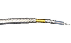
** Images are for display purposes only refer to Product Technical Details for accurate information on the product.
In the case the material only comes in a predetermined color or doesn’t come with any color
Product Details
Dielectric: Solid PTFE
Inner braid: flat silver plated copper strip
Interlayer: aluminum polyimide or polyester tape
Outer Braid: Round silver plated copper
Jacket: FEP, translucent colors, solid colors or clear
Operating temperature: -55 +200° C
Velocity of Propagation: 70%
Impedance: 50 Ohms
Capacitance:29.4 pF/f
Shielding Effectiveness: <-95 db
| Center conductor |
Center conductor diameter (in.) |
Bend radius (in.) |
Part Number | Action |
| SCCS | .020 (7/.0067) | 0.5 | SB316 | Request A Quote |
| SCCS | .037 Solid | 1.0 | SB142 | Request A Quote |
| SCCS | .037 Solid | 0.9 | SB142i | Request A Quote |
| SPC | .0385 (19/.008) | 1.0 | SB400 | Request A Quote |
| SCCS | .059 Solid | 1.4 | SB304 | Request A Quote |
| SPC | .094 (7/.031) | 2.0 | SB393 | Request A Quote |
| Attenuation (dB/100ft) @ | Typ | Typ | Typ | Typ | Typ | Typ |
| 400 MHz | 14.5 | 6.4 | 6.4 | 6.8 | 5.0 | 3.8 |
| 1 GHz | 23.3 | 10.5 | 10.5 | 11.1 | 8.3 | 6.4 |
| 2 GHz | 33.5 | 15.5 | 15.5 | 16.2 | 12.3 | 8.5 |
| 3 GHz | 41.6 | 19.5 | 19.5 | 20.4 | 15.6 | 12.6 |
| 5 GMHz | 54.8 | 26.3 | 26.3 | 27.5 | 21.3 | 17.6 |
| 10 GHz | 80.4 | 40.1 | 40.1 | 41.8 | 33.0 | - |
| 18 GHz | 112.4 | 58.3 | 58.3 | 60.6 | 48.8 | - |
Harbour’s SB coaxial cables have been designed for low attenuation at high frequencies, while using similar dimensions to MIL-DTL-17 constructions. Standard connectors may frequently be used, thereby avoiding tooling charges.
Solid PTFE dielectrics are manufactured with tight tolerances to ensure impedance uniformity and to effect VSWR levels that meet or exceed MIL-DTL-17 specifications for cables of comparable size. The strip braid configuration is by far the most effective means of lowering attenuation levels of coaxial cable at high frequencies while providing shielding effectiveness levels that exceed those of flexible MIL-DTL-17 cables. Flat strips of silver plated copper are braided over the dielectric core, frequently with an intermediate metallized polyester or polyimide layer, and an outer round wire braid. This shielding technique provides superior shielding effectiveness and lower transfer impedance than any standard double braided mil-spec construction.
FEP jackets are typically used, but alternate designs are available such as flame retardant PVC and abrasion resistant overall braids. Marker tapes or surface printing are used for positive identification.
The chart on the following page outlines just a few designs Harbour manufactures. Some of the more popular constructions are standard stock items, and many additional cables are available for prototype assemblies. Many cables not referenced have been designed to meet specific customer requirements.
Attenuation Calculation and K Factors: Although typical and maximum attenuation values are given for discrete frequencies, typical attenuation values may be calculated by using K1 and K2 factors for each construction. The K1 factor is calculated by taking into consideration the type, strand factor, and diameter of the center conductor, and the impedance of the cable. The K2 factor is calculated by taking into consideration the velocity of propagation and the dissipation factor of the dielectric.
Formula for Calculating Attenuation using K Factors: Attenuation (dB/100 ft) at any frequency (MHz) = (K1 x root of frequency + (K2 x frequency)
| - | SB316 | SB142/SB142i | SB400 | SB304 | SB393 |
| K1 | .705 | .305 | .319 | .231 | .164 |
| K2 | .00099 | .00099 | .00099 | .00099 | .0012 |