
Harbour RF Microwave SS Rock SSTable Spiral Strip Coaxial Cable
Harbour RF Microwave SS Rock SSTable Spiral Strip Coaxial Cable
SKU: SKU:
- Harbour RF Microwave SS Rock SSTable Spiral Strip Coaxial Cable
- Harbour RF Microwave SS Rock SSTable Spiral Strip Coaxial Cable
Couldn't load pickup availability
*Data provided on this page is subject to change based on different manufacturers' variances
** Images are for display purposes only refer to Product Technical Details for accurate information on the product.
In the case the material only comes in a predetermined color or doesn’t come with any color
Center conductor: Solid silver plated copper clad steel
Dielectric: Solid PTFE
Inner shield: Spiral strip of silver plated copper
Outer Braid: Round silver plated copper
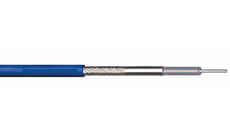
Jacket: Solid blue FEP
Operating temperature: -55 +200° C
Velocity of Propagation: 70%
Shielding Effectiveness: <-110 db
| Center conductor diameter (in.) |
Dielectric diameter (in.) |
Capacitance (pF/ft) |
Part Number |
| .037 | .117 | 29.4 | SS402 |
| .0201 | .064 | 29.4 | SS405 |
| .0113 | .064 | 19.5 | SS75086 |
| Attenuation (dB/100ft) @ | Typ | Typ | Typ |
| 400 MHz | 6.4 | 11.9 | 12.4 |
| 1 GHz | 10.5 | 19.2 | 19.9 |
| 2 GHz | 15.5 | 27.7 | 28.8 |
| 2.4 GHz | 17.2 | 30.6 | 31.7 |
| 3 GHz | 19.5 | 34.5 | 35.8 |
| 5 GMHz | 26.3 | 45.7 | - |
| 10 GHz | 40.1 | 67.5 | - |
| 18 GHz | 58.3 | 95.1 | - |
Harbour’s SS coaxial cables are flexible alternatives to semi-rigid coax, and the unique shielding configuration offers a cost effective, low attenuation option. The use of strip/round braid composite shields results in low transfer impedance levels. The 50 ohm constructions exhibit the same attenuation characteristics as the M17/130-RG402 and M17/133-RG405 cables. All SS cables have VSWR characteristics that meet or exceed similar size flexible constructions. SS402 and SS405 have been designed with diameters over the outer braids of .141” and 086” respectively, so standard SMA connectors may be used.
An overall FEP jacket is resistant to oil and chemicals. The cable is either unmarked or surface printed eliminating a marker tape that may cause problems in termination. Without the marker tape, an improved level of adhesion exists between the braided core and the jacket that allows ease of termination with short length assemblies.
Attenuation Calculation and K Factors: Although typical and maximum attenuation values are given for discrete frequencies, typical attenuation values may be calculated by using K1 and K2 factors for each construction. The K1 factor is calculated by taking into consideration the type, strand factor, and diameter of the center conductor, and the impedance of the cable. The K2 factor is calculated by taking into consideration the velocity of propagation and the dissipation factor of the dielectric.
Formula for Calculating Attenuation using K Factors: Attenuation (dB/100 ft) at any frequency (MHz) = (K1 x root of frequency + (K2 x frequency)
| - | SS402 | SS405 | SS75086 |
| K1 | .302 | .576 | .599 |
| K2 | .00099 | .00099 | .00099 |