
Harbour RF Microwave LL Coaxial Cable Solid Center Conductors
Harbour RF Microwave LL Coaxial Cable Solid Center Conductors
SKU: SKU:
- Harbour RF Microwave LL Coaxial Cable Solid Center Conductors
- Harbour RF Microwave LL Coaxial Cable Solid Center Conductors
Couldn't load pickup availability
*Data provided on this page is subject to change based on different manufacturers' variances
** Images are for display purposes only refer to Product Technical Details for accurate information on the product.
In the case the material only comes in a predetermined color or doesn’t come with any color
Product Details
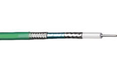
Center Conductor: Solid silver plated copper
Dielectric: Expanded PTFE tape
Inner Braid: Flat silver plated copper strip
Interlayer: Aluminum polyester or polyimide tape
Outer Braid: Round silver plated copper
Jacket: FEP, translucent colors, solid colors or clear
Operating temperature: -55 +200° C
Velocity of Propagation: 80%-83%
Impedance: 50 Ohms
Capacitance: 25.0 pF/ft
Shielding Effectiveness: <-95 db
| Center conductor diameter (in.) |
Dielectric diameter (in.) |
Bend radius (in.) |
Part Number | Action |
| .0286 | .080 | 0.6 | LL120 | Request A Quote |
| .0403 | .110 | 0.8 | LL160 | Request A Quote |
| .051 | .145 | 1.0 | LL142 | Request A Quote |
| .057 | .160 | 1.2 | LL235 | Request A Quote |
| .089 | .250 | 1.7 | LL335 | Request A Quote |
| .089 | .250 | 1.5 | LL335i | Request A Quote |
| Attenuation (dB/100ft) @ | Typ | Typ | Typ | Typ | Typ | Typ |
| 400 MHz | 8.3 | 6.3 | 4.7 | 4.2 | 2.9 | 2.9 |
| 1 GHz | 13.1 | 10.0 | 7.5 | 6.7 | 4.6 | 4.6 |
| 2 GHz | 18.7 | 14.3 | 10.7 | 9.6 | 6.6 | 6.6 |
| 3 GHz | 23.0 | 17.7 | 13.2 | 11.9 | 8.2 | 8.2 |
| 5 GMHz | 29.9 | 23.1 | 17.2 | 15.5 | 10.8 | 10.8 |
| 10 GHz | 42.8 | 33.4 | 24.9 | 22.5 | 15.8 | 15.8 |
| 18 GHz | 58.2 | 46.0 | 34.2 | 31.0 | 21.9 | 21.9 |
Unique cable design: The braid configuration and the expanded PTFE dielectrics of the LL cable constructions contribute to lower attenuation levels at higher frequencies, while providing shielding effectiveness levels that exceed those of flexible MIL-DTL-17 cables. Flat strips of silver plated copper are braided over the dielectric core with an intermediate metallized polyester or polyimide layer, and an outer round wire braid.
Excellent electrical characteristics: All of Harbour’s LL cables with expanded PTFE dielectrics exhibit low coefficients of expansion over the entire operating temperature range from -55° C to +200° C. Impedance discontinuities are minimized at the cable-to-connector interface. Higher levels of power can be transmitted because higher temperatures do not affect the cable due to the thermal stability of the tape. Where phase versus temperature requirements are critical, Harbour’s LL cables allow for an approximately 75% lower phase shift and change in propagation time delay due to temperature. Temperature cycling tests have been performed on a number of Harbour’s cables with positive results.
Lowest attenuation for any given size: Harbour’s LL coaxial cables, with expanded PTFE dielectrics and strip braid composite configurations, offer attenuation from 20 to 35% below other mil spec cables of comparable size. When size and weight are considerations, Harbour’s LL cables should be specified.
Attenuation Calculation and K Factors: Although typical and maximum attenuation values are given for discrete frequencies, typical attenuation values may be calculated by using K1 and K2 factors for each construction. The K1 factor is calculated by taking into consideration the type, strand factor, and diameter of the center conductor, and the impedance of the cable. The K2 factor is calculated by taking into consideration the velocity of propagation and the dissipation factor of the dielectric.
Formula for Calculating Attenuation using K Factors: Attenuation (dB/100 ft) at any frequency (MHz) = (K1 x root of frequency + (K2 x frequency)
| - | LL120 | LL160 | LL142 | LL235 | LL335/LL335i |
| K1 | .410 | .309 | .231 | .207 | .141 |
| K2 | .0001785 | .00025 | .0001785 | .0001785 | .0001674 |